I’ve just completed a pretty easy farkle… for the last 7 years I’ve carried a remote control for my garage door in my bike jacket pocket. As I approach home I use my right-hand (coasting) to push the button. It’s only a summer vented jacket. So, if it’s rainy I’ll also have a rain jacket over the top and, of course, wet-weather riding gloves which causes problem pressing that pesky little button.
So, borrowing a few ideas from the interweb, I can now open my garage door by flashing my bike’s hi-beam:
Now that I’ve done it, I wish I’d done it years ago. Here’s the how-to:
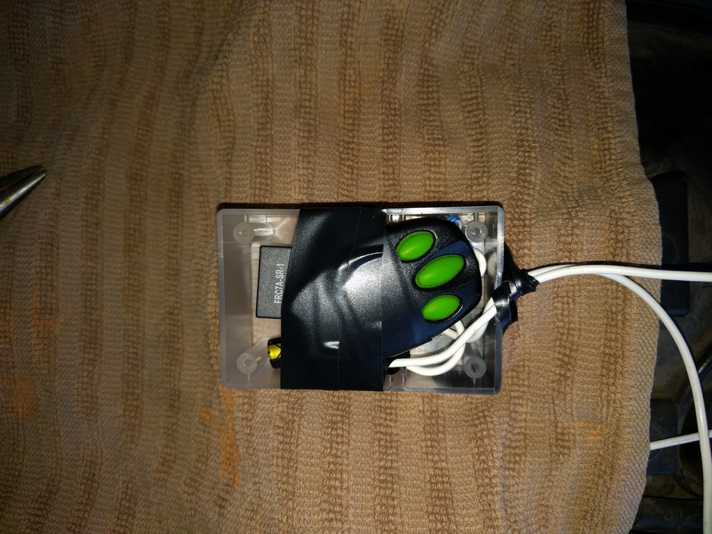
Open up the remote control fob and locate the contact point for the push button (mine has 3 buttons). Trace the circuit and locate a solder joint for each. Solder 2 thin wires to each: be careful as the tracks are super thin. For the wires, I actually used some stripped cores from an old ethernet cable (I’m lazy and cheap). Feed the wires outside the casing and close it back up. Note that my existing button continues to work. Sorry – no photo for this – but I’ll grabe some soon and update.
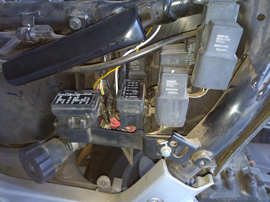
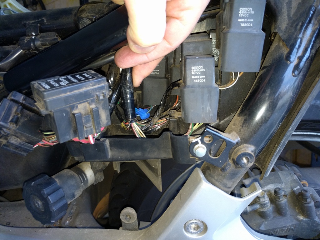
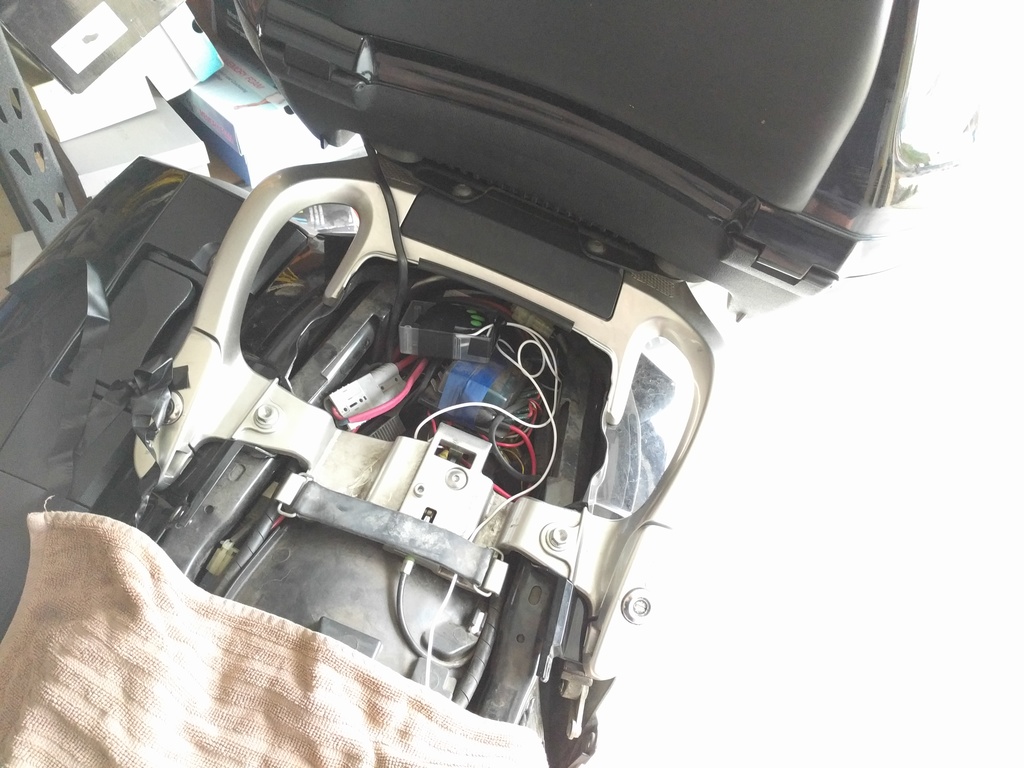
Connect a lead to the wire coming from the hi-beam switch into the hi-beam relay. See photos from ST-Owners for access to the relay here. Here, you can see mine (I just used one of these clamps with a spade connector):
Run the lead through the frame and backwards to the area under the seat.
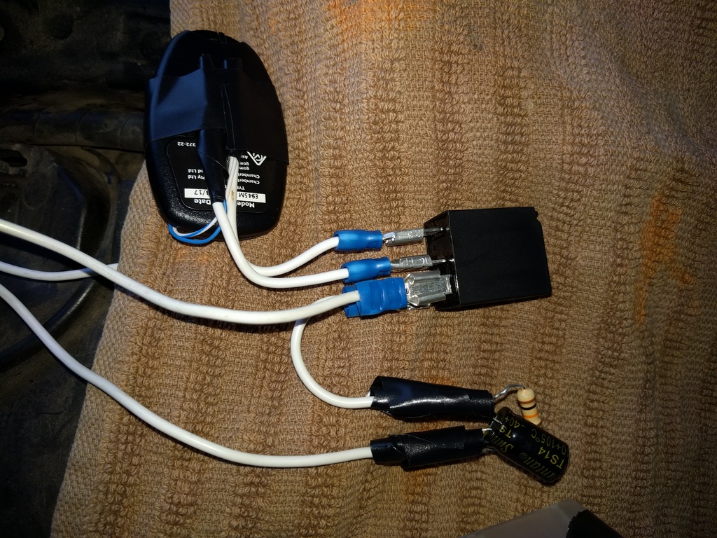
Get a standard horn-relay – it doesn’t need to be high-current as it’s passing bugger-all through it (from a 3V battery in your remote) and wire it up as shown here (forget the fuse):
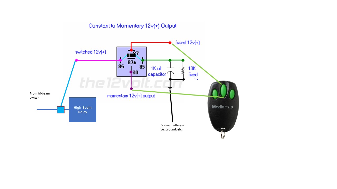 The capacitor/resistor will ensure that even if you turn on your high-beam (instead of just flashing) then only a momentary pulse is sent to the remote control. If you don’t include the capacitor/resistor and just wire it directly to the earth then running high-beam for a long time may flatten your remote’s battery. The relay, 1000uF polarized capacitor, and 10K resistor will cost <$10 from JayCars.
The wire from the high-beam switch is connected to pole 86 (pink), and the ground pole 85 is run through the capacitor/resistor then to the bike’s ground/frame/-ve.
Then, the 2 wires from your remote control are connected to poles 87 and 30 (it doesn’t matter which as it’s just closing a circuit).
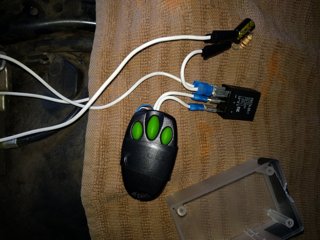
Here’s the finished product (just a working prototype – I will clean it up, make sure contacts are insulated, etc…. one day, maybe).
Enjoy!